+86-15722819198
Name : FUET-5030
Type : Electromagnetic Buzzer
Drive Mode : Passive Buzzer
Technology : Smd Buzzer
Size : 3-5mm
A. SCOPE
This specification applies magnetic buzzer, FUET-5030
B. SPECIFICATION
| No. | Item | Unit | Specification | Condition |
1 | Oscillation Frequency | Hz | 4000 | Vo-p=1/2duty , square wave |
2 | Operating Voltage | Vo-p | 2 ~ 4 | |
3 | Rated Voltage | Vo-p | 3 | |
4 | Current Consumption | mA | MAX.110 | at Rated Voltage |
5 | Sound Pressure Level | dB | MIN. 75 | at 10cm at Rated Voltage |
6 | Coil Resistance | Ω | 12±3 | |
7 | Operating Temperature | ℃ | -30 ~ +70 | |
8 | Storage Temperature | ℃ | -40 ~ +85 | |
9 | Dimension | mm | 5.0 x 5.0 x H3.0 | See appearance drawing |
10 | Weight (MAX) | gram | 0.6 | |
11 | Housing Material | LCP( Black ) | ||
12 | Leading Pin | Tin Plated Brass(Sn) | See appearance drawing | |
13 | Environmental | RoHS |
C. APPEARANCE DRAWING 
Tol : ± 0.3 Unit: mm
D.TESTING METHOD
Standard Measurement conditions
Temperature:25±2℃ Humidity:45-65%
Acoustic Characteristics:
The oscillation frequency, current consumption and sound pressure are measured by the measuring instruments shown below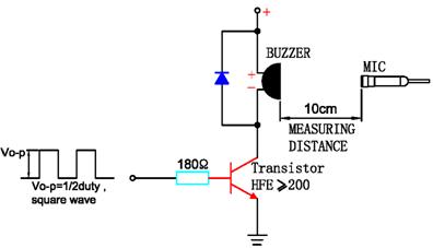
In the measuring test, buzzer is placed as follows:
E. Typical Frequency Response Curve
F. Recommend Driving Circuit 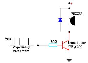
The base current Ib should high enough so that it saturates the collector current of the transistor with the CB load.
G. Soldering Condition
(1)Recommendable reflow soldering condition is as follows
(Reflow soldering is twice)
Note:It is requested that reflow soldering should be executed after heat of product goes down to normal.
Heat resistant line
(Used when heat resistant reliability test is performed)
(2)Manual soldering
Manual soldering temperature 350 ℃ within 5 sec.
H. RELIABILITY TEST
NO. | ITEM | TEST CONDITION AND REQUIREMENT |
1 | High Temperature | After being placed in a chamber with 85 |
2 | Low Temperature | After being Placed in a chamber with -40 |
3 | Humidity Test | After being Placed in a chamber with 90-95% R.H. at 40 |
4 | Temperature Cycle | The part shall be subjected to 5 cycles. One cycle shall be consist of: |
5 | Drop Test | Drop on a hard wood board of 4cm thick, any directions ,6 times, at the height of 75cm . |
6 | Vibration Test | After being applied vibration of amplitude of 1.5mm with 10 to 55 Hz band of vibration frequency to each of 3 perpendicular directions for 2 hours . |
7 | Solderability | Lead terminals are immersed in rosin for 5 seconds and then immersed in solder bath of +300 |
8 | Terminal Strength | The force of 9.8N(1.0kg) is applied to each terminal in axial direction for 10 seconds. |
TEST CONDITION.
Standard Test Condition : a) Temperature : +5 ~ +35℃ b) Humidity : 45-85% c) Pressure : 860-1060mbar
Judgment Test Condition : a) Temperature : +25 ± 2℃ b) Humidity : 60-70% c) Pressure : 860-1060mbar
I. PACKING STANDARD 
Linkman:Tracy Wu
Mobile:15722819198
Tel:0755-83253369
Fax:0755-83253369
Email:fsdzfmq@163.com

 2℃ for 96 hours and then being placed in normal condition for 2 hours.
